A photographic point cloud is built by comparing overlapping images. The camera does not record a 3D point directly, software estimates its position from the way the same surface appears in different views.
This helps explain some familiar results. A brick wall may reconstruct clearly while the glass beside it contains gaps. A roof can look complete even when the wall underneath is largely missing. Both outcomes depend on what the photographs show and how reliably those views can be matched.
The exact implementation varies between processing systems, but a typical workflow has four main stages.
1. Find features that appear in several photographs
Processing begins by looking for distinctive image features: corners, patches of texture and other details that can be recognised in another photograph. Candidate matches are checked for geometric consistency so that similar-looking but unrelated features are less likely to be accepted.
For example, consider a painted marking beside a warehouse. As the drone moves, the marking appears in different parts of successive images. If the software can identify it consistently, it becomes one of many connections between those images.
A plain white section of the same yard may offer fewer useful features. Repeated patterns can also be difficult: many similar roof panels may look interchangeable unless surrounding detail helps distinguish them.
This is why image quality matters before any dense model is created. Motion blur removes small features, while poor overlap leaves too few shared observations. More photographs elsewhere on the site do not necessarily fix the weak connection.
2. Estimate the camera positions and the initial 3D structure
The matched features help the software estimate where each photograph was taken and how the camera was oriented. It also estimates an initial set of 3D positions for the shared features. These estimates are refined together so the reconstructed points project back to consistent locations in the images.
This stage is commonly called structure from motion. It produces a relatively sparse reconstruction used to establish camera geometry, not the final detailed point cloud.
Camera calibration matters here too. The way a lens projects the scene onto the sensor must be accounted for, otherwise errors can affect the reconstructed geometry.
Photographic reconstruction alone does not establish a known real-world scale and location. Camera position information or other suitable reference measurements are needed to place and scale the model. The available constraints and their quality determine how reliably that can be done.
At this stage, a disconnected group of photographs is an important warning. If one side of a building cannot be linked to the rest of the image set, it may remain separate or fail to reconstruct. Adding detail later will not repair an unresolved alignment simply by producing more points.
3. Estimate depth across the visible surfaces
Once the camera geometry is established, the software can compare corresponding image regions in more detail to estimate surface depth. A common approach is to calculate depth maps for overlapping views and then combine compatible estimates into a denser 3D result.
Agisoft's photogrammetry workflow tutorial describes depth-map calculation as part of dense cloud generation. The important distinction is that this stage uses image information to estimate additional geometry; it does not simply fill the space between the sparse tie points with evenly spaced dots.
Think of the warehouse wall again. The sparse stage may have established the camera positions using strong features around corners and openings. Dense reconstruction can then recover more of the wall's textured surface, provided those areas are visible in suitable overlapping photographs.
A covered loading bay is different. If the interior never appears clearly in the images, there is no reliable photographic evidence for its shape. It may remain empty even while the surrounding facade is dense.
4. Filter inconsistent estimates and assemble the cloud
Depth estimates from different views will not agree perfectly. Filtering helps reject inconsistent or isolated results before or during assembly of the point cloud. The remaining points can be assigned colour from the photographs and written to an output file.
Filtering involves a trade-off. Retaining weak estimates can leave noise around edges and difficult surfaces. Stronger filtering can remove some genuine fine detail along with the unreliable points.
For a user inspecting the output, the question is whether the required features are represented clearly enough for the job. A railing partly removed by filtering is still incomplete geometry. A dense group of scattered points around it is not necessarily a better measurement surface.
MapperTool provides a browser view of the finished point cloud and exports it as LAZ. Its point cloud documentation describes the output and capture considerations.
What determines point density?
Point density depends on both the photographs and the processing. Flying closer can capture finer surface detail, while sharp images, useful viewing angles and suitable overlap help that detail reconstruct. Dense-processing settings affect how much of the available detail is retained.
Density also varies within one project. A textured wall photographed well may contain many points, a reflective window or partly hidden surface may contain few. A total point count for the site does not tell you whether a particular pipe, roof edge or ground patch is adequately represented.
When comparing results from 3D mapping software, inspect the same features at a similar viewing scale. Do not choose a result only because its file is larger. Ask whether the extra points describe more consistent geometry or simply include more noise.
What common defects can tell you
What you see | What to check |
|---|---|
A missing wall beneath a complete roof | Whether the flight included enough views of the wall |
Gaps or scattered points on windows and water | Reflections and changes in appearance between views |
Doubled edges or displaced surfaces | Alignment, movement in the scene and reference consistency |
Weak detail near the survey boundary | Image coverage and the number of useful views there |
Vegetation that looks rough or fragmented | Movement, occlusion and repetitive texture |
Using the point cloud map
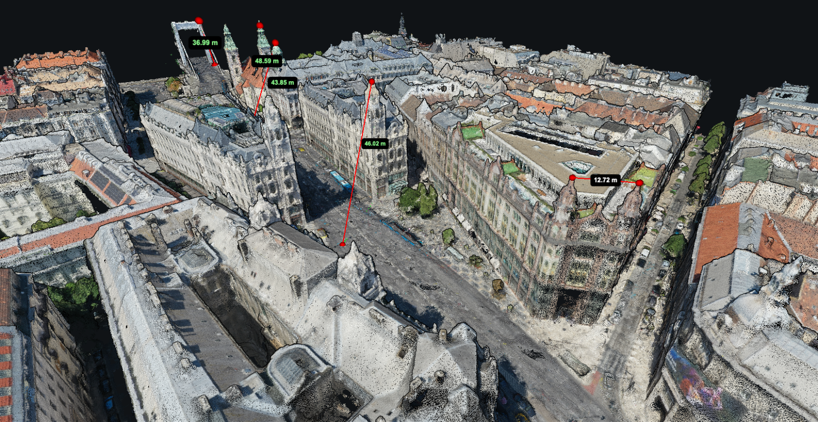
A point cloud map can support 3D inspection and further work in compatible software, but measurements still depend on coverage and accuracy. Check that both endpoints of a height or clearance measurement are actually represented. An empty space beneath an object is not a measured underside.
Point spacing is also different from positional accuracy. Closely packed points can still share a systematic offset. The guide to drone survey accuracy explains how to distinguish image resolution, internal measurement quality and real-world position.
If the client expects a solid, textured model, confirm whether they need a mesh rather than a cloud. See point cloud or 3D mesh for the delivery differences.
For the next flight, use any important gaps in the current cloud to identify missing viewpoints. The photo-count and overlap guide can help you plan the coverage. Where the camera never observed a surface, better photographs are more useful than repeatedly increasing the processing settings.