A roof is easy to outline on a map. Measuring the length of its slope is a different task, because the ridge and eaves sit at different heights. A point cloud keeps those height differences, so you can work with the building's three-dimensional shape instead of its footprint alone.
That makes 3D measurement useful for plenty of ordinary site questions: how tall a retaining wall is, how far a bank rises, or whether a tree stands higher than a nearby roof. The result depends on two things: choosing the measurement that answers the question, and having enough reliable points on the surfaces involved.
Below are six common examples, including the details that are easy to miss when placing a measurement.
First, decide which distance you need
Two points at different heights can give you three useful numbers: their horizontal separation, their vertical difference and the straight-line distance between them in 3D.
For example, imagine the edge of a ramp is 4 metres away horizontally and 3 metres higher. Its straight inclined length is 5 metres. All three numbers are correct, but they describe different things. You would use the vertical difference to describe the rise, the horizontal distance for its plan dimensions, and the inclined length for the straight ramp surface.
A line between two points does not automatically follow every dip and bump between them. On uneven ground, a series of shorter segments can approximate a route more closely. A detailed surface-length calculation needs a method that actually follows the reconstructed surface.
This distinction also applies to area. The area seen from above, the area of a sloping plane and the area of an irregular surface are different quantities. Before using any online measure tool, check which one it calculates.
Six practical uses for 3D measurement
1. Roof slope length and roof height
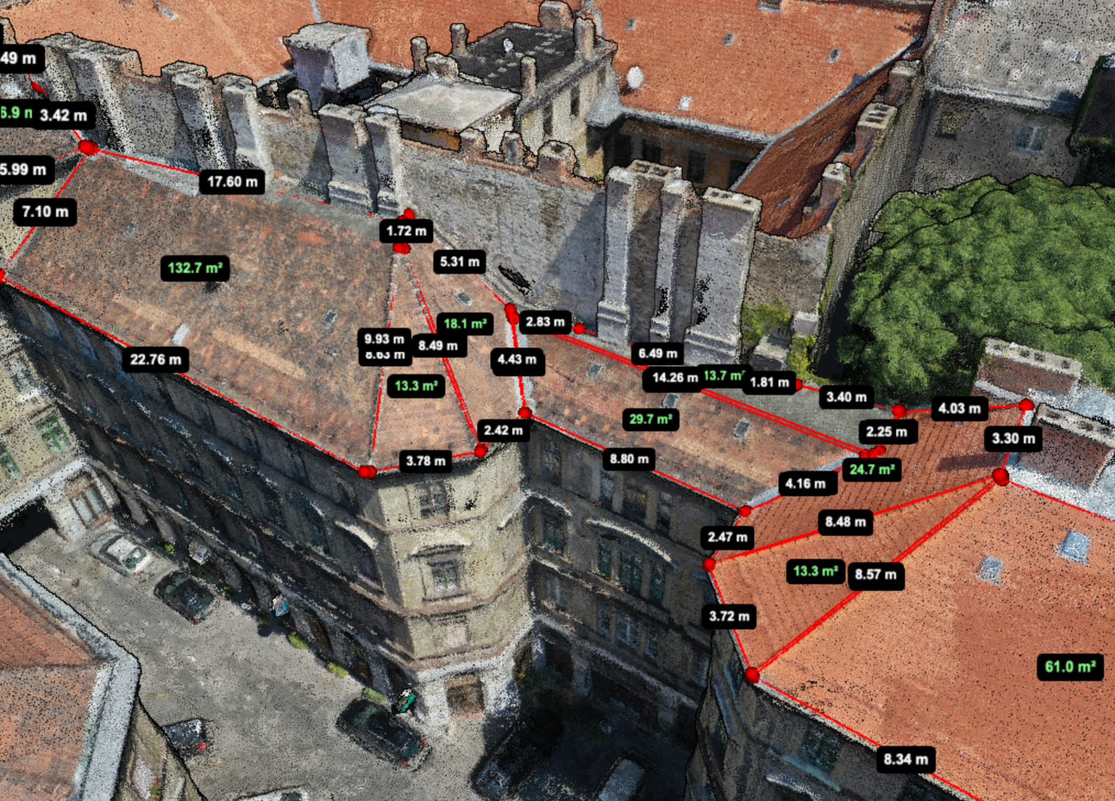
On a simple pitched roof, points along the ridge and eaves let you examine the rise and inclined dimensions. Work on one roof face at a time, especially where extensions or dormers interrupt the main plane.
For a sloping area measurement, the chosen boundary and calculation need to represent that roof face in 3D. A polygon drawn around the entire building from above gives a different quantity. Neither measurement includes details such as tile overlap or material waste, so a geometric area is only one input to an order for roofing materials.
Check the ridge from an oblique view before placing an endpoint. Chimneys, nearby branches and scattered reconstruction points can make the highest visible point a poor choice. A clear ridge line is more useful than one isolated dot above it.
2. Wall dimensions and facade area
A point cloud can represent vertical walls that occupy almost no area in a top-down map. If the wall has reconstructed clearly, you can measure its height and width or define its plane for an area calculation.
Be specific about the area you need. The gross area of a rectangular wall includes its windows and doors. Net cladding area requires subtracting those openings, and recessed sections may need separate treatment. Drawing a boundary around a facade does not automatically identify every opening inside it.
Coverage is often the limiting factor. A flight looking straight down may capture the roof well while leaving the wall sparse. MapperTool's point cloud capture guidance recommends oblique views as well as the nadir grid to improve coverage of vertical surfaces.
3. The height and shape of an embankment or cutting
At a road cutting, the crest and toe are useful reference features. Their elevation difference describes the bank's rise; a line across a straight face describes its inclined length. Following the crest along the road answers another question again.
The difficult part is often deciding where the feature begins. Loose material at the toe or vegetation along the crest can blur the boundary. Rotate the cloud and inspect several nearby sections before choosing the points you will report.
For a longer cutting, one measurement rarely represents the whole face. Record dimensions at named locations, or use dedicated software to extract cross-sections where the job needs a continuous profile. That gives a designer more context than a single maximum height selected somewhere along the site.
4. Individual tree height
Tree height is the vertical difference between the top of the tree and the ground at its base. The elevation of the crown alone is not the tree's height, and the distance from the crown to an arbitrary point on a nearby road may be misleading on sloping ground.
A photographic point cloud often captures the canopy more readily than the ground beneath it. If the base is hidden, you need a defensible ground reference from another source or a separate measurement. Interpolating the ground from nearby visible patches is an estimate, whose suitability depends on the terrain.
Inspect the crown too. A few floating points above the branches can exaggerate the result, while missing fine branches can make it too low. For a tree beside a building, distinguish the question “How tall is the tree?” from “How far does its crown extend above this roof?” The reference level changes the answer.
5. Clearance beneath a gantry or overhang
A point cloud can help examine clearance when both the underside of the structure and the surface below it have been captured. A conventional overhead flight may record the gantry's top while seeing none of its underside. Rotating the finished model cannot reveal geometry that was never reconstructed.
When the required surfaces are present, measure the relevant vertical gap and check more than one location. The ground may rise across the opening, and a beam or fitting may sit lower than the rest of the structure. A diagonal line to an adjacent point will not give the vertical clearance at the location of interest.
If the underside is missing, record that limitation and arrange suitable additional capture or a direct site measurement. Do not estimate it by subtracting an assumed beam thickness from the visible top.
6. Stockpile dimensions and volume
A cloud is useful for inspecting a stockpile's shape, locating its toe and checking whether machinery or vegetation obscures the edge. Height and width measurements can help describe it. Volume, however, needs a defined upper surface, a boundary and a base surface; it cannot be obtained simply by counting points.
MapperTool's map volume tool uses the DSM, so select that output if you need this calculation. It is separate from measuring distances in the cloud. The measurement documentation describes this requirement, while our stockpile volume workflow covers the choices around the pile boundary and base.
Taking the measurements in MapperTool
For a project containing a point cloud, open 3D point cloud in the viewer. Distance, area and height tools are available there, and results appear in the Measurements tab. The viewer guide explains navigation and display controls.
Start with a view that makes the target surface easy to identify. After placing a measurement, rotate the scene to check the endpoints from another angle. A point that looks correctly placed from the front may actually be on a surface behind the one you intended.
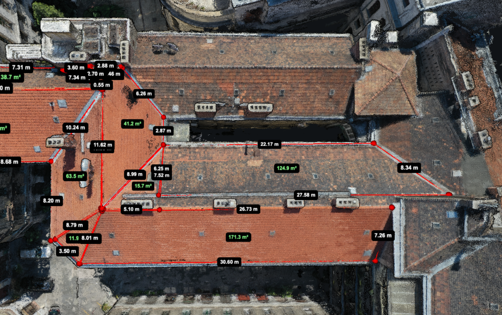
Name the result so another person knows what it means. “North retaining wall — height at east end” is more useful than “Height 4”. Include the reference location when it matters, particularly for trees, sloping ground and clearance checks.
Before you use the number
The number of decimal places in a label is not a statement of survey accuracy. A dense cloud can still contain positioning errors, and a clearly defined measurement can still use a poorly reconstructed edge. Our article on drone survey accuracy explains why image detail, scale and independent checks need to be considered separately.
Before reporting a result, check that the required surfaces exist, that the endpoints belong to those surfaces, and that you selected the correct quantity. Where the decision depends on a small difference, compare against suitable independent site measurements rather than relying on how convincing the model looks.
You can process a survey in MapperTool and inspect the point cloud alongside the map outputs. For a first check, choose a clearly visible feature with a known dimension, then move on to the less accessible parts of the site.